MONITORING OF UNEARTHED SUPPLY SYSTEMS BY APPLICATION OF THE HIG INSULATION MONITORING DEVICE PRODUCED BY THE HAKEL COMPANY
PART 5: A NEW TYPE OF MONITORING DEVICE FOR HEALTHCARE
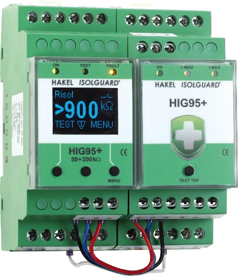
In the fifth part of the series on the application of HIG devices for monitoring insulation status, we introduce a new type device – the HIG95+, specially designed for healthcare facilities.
Demands in healthcare
Demands for the correct operation of IT supply systems in healthcare are laid down by the IEC 60364-7-710:2002 standard on facilities in the healthcare area. The healthcare unearthed system is used for the power supply of electrical instruments and systems used in life supporting equipment, surgical applications and other instruments in the patient environment. This applies for all areas falling under Group 2 of healthcare – typically for operating theatres and intensive care units. The standard also provides details on the correct operation of this type of system, such as monitoring insulation resistance with insulation monitoring devices and the obligation to monitor and signal the current and thermal overload of the medical transformer. In the past, the HAKEL Company ensured this obligation with a separate TOM product, which was connected to the same signal panel as the insulation status monitoring device.
Connection and principle of the monitoring device
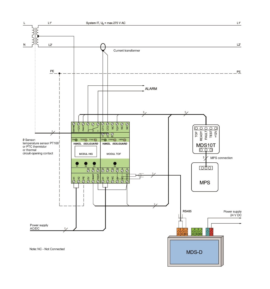
Implementation of this function in a single product is offered directly, particularly with development of external communication of the devices on the RS485 line. Consequently, the HIG95+ device, just like the HIG 97, was extended by an expander called the MODUL TOF (Temperature and Overload Failure), which enabled the possibility of current and temperature monitoring. The temperature can be detected by a PT100 resistance temperature sensor, a PTC thermistor or connection of a thermal circuit-opening contact. The sensor is selected on the menu of the monitoring device. The current load is detected by a current transformer – the following conversion ratios can be used and set on the menu: 25/5, 40/5, 50/5, 60/5, 80/5 and 100/5.
The TOF module has one green LED light, which signals a connected power supply and two yellow lights signalling thermal overload and excessive current load on the medical transformer. The module also offers outlet terminals for contact of temperature and current fault to the MDS10T LED signalling panel and terminals for a twisted pair of the RS485 interface. They can be used for connection to any higher user system (e.g. supervisory control and data acquisition – SCADA), including a new MDS-D LCD panel.
The primary HIG module is used to control the equipment using the buttons and LCD display, where all parameters can be intuitively adjusted. This module also powers the MDS10T LED panel, offers one signal free 230 V AC / 1 A change-over contact and a terminal for connection of the transformer’s centre tap or, potentially, an artificially created centre tap by TL inductors. As like all other HIG devices, it has a green LED light indicating power connection and two yellow LED lights signalling a fault of the insulation status and activation of the monitoring device internal test.
Both models require power supply from 90 to 265 V AC (47 to 440 Hz) or 90 to 370 V DC.
New signalling panel
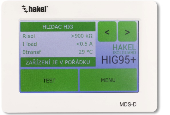
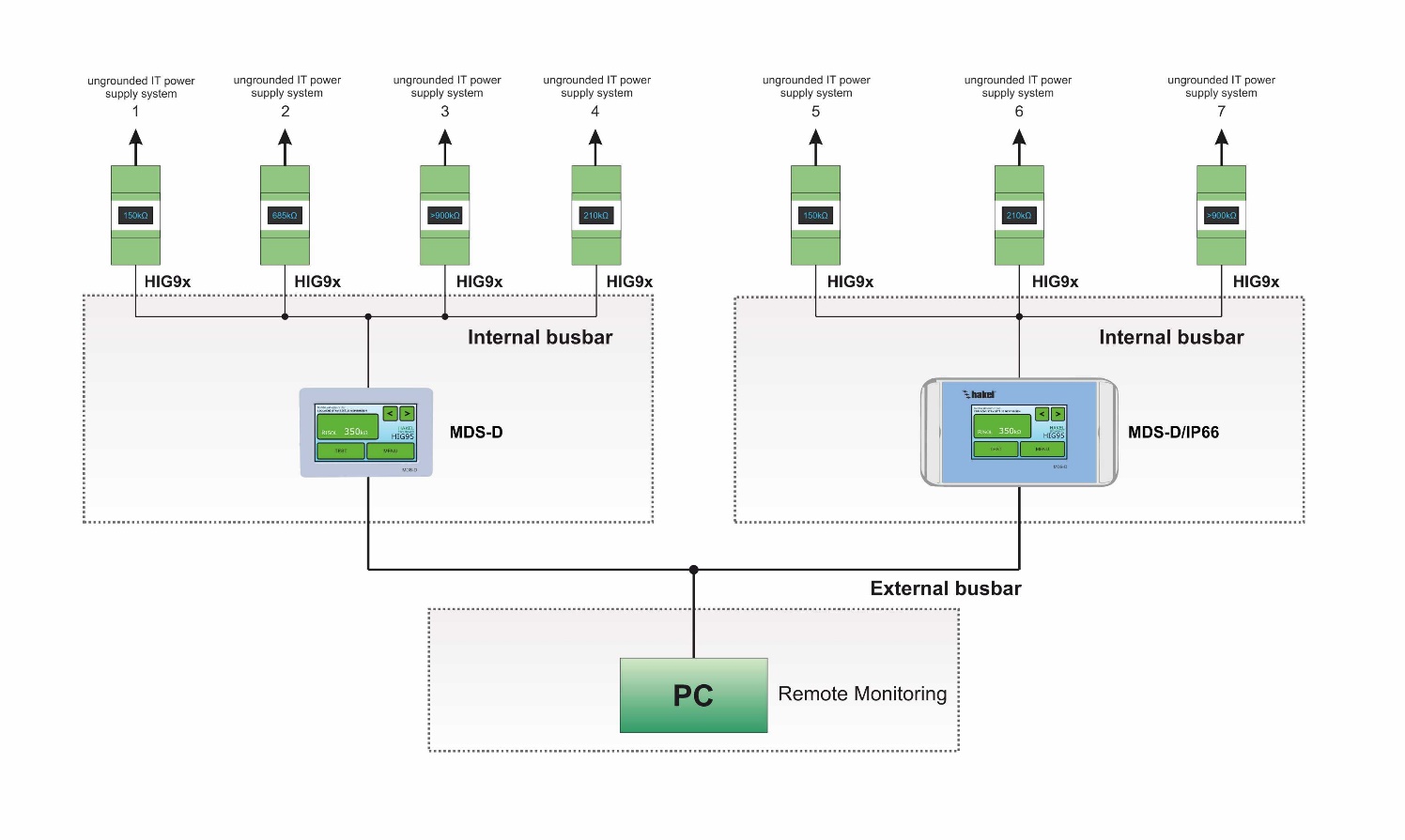
In addition to the new HIG95+ monitoring device, the HAKEL Company has also launched the new MDS-D signalling panel with an LCD touch screen. This panel displays values from up to 24 different HIG monitoring devices including the current consumption and temperature of the medical transformer. Thus, there is no problem to monitor all 3 of the values from multiple devices on a single panel. The individual monitoring devices can be named, e.g. according to their location in the hospital, and the LCD touch screen can control the acoustic and visual signalling of a fault and a remote test. The panels are currently available in IP20 and IP66 variants.
The MDS-D panel communicates with the HIG monitoring devices on an internal RS485 busbar where user intervention is not required. The ISOLGUARD protocol has been implemented there and communication with the devices is fully automatic, including the ability to search for devices newly connected to the busbar. Each connected monitoring device on the busbar must have a unique address, which can be easily set up using the menu directly on the device.
For external communication with a higher user system, the panel is equipped with another RS485 line. Communication then proceeds by means of telegrams received from the PROFIBUS protocol.
Example of connection and communication of monitoring devices via the RS485 busbar
Settings and visualisation
As mentioned above, the monitoring device can be easily set up with buttons on an integrated display. Alternatively, it can be remotely set up remotely via the RS485 line. The critical insulation resistance is adjustable between 50 kΩ and 200 kΩ, and the display shows it from 5 to 900 kΩ. An IEC 61557-8 requirement for monitoring devices in healthcare IT supply systems specifies the signalisation of reduced insulation resistance on the level of 50 kΩ, which is the most frequently adjusted value in healthcare facilities.
Hysteresis of the monitored Rhyst insulation resistor can be set from 0 to +100% Rcrit, while hysteresis of the current load is set from 0 to +20% Icrit. If the PT100 sensor is used, it is possible to use hysteresis of 0 to 20% ?crit. The reaction delay for signalling the tON insulation status is between 0-60 s, with the increment of 1 s. The reaction delay in signalisation for temperature and current faults can be adjusted in the same way.
The range of the visualised value of the Iload current load is from 0.5 A to 100 A depending on the type of measurement transformer; the critical value of the Icrit current load is adjustable according to the type of current transformer in increments of 1 A. The temperature range of the visualised isolation transformer ?transf is from 5 to 190°C (only for PT100) and the critical temperature of the separating transformer ?crit for the resistance temperature sensor PT100 is adjustable from 70 to 130°C. The determining level for the PTC thermistor and the thermal circuit-opening contact is 1.6 kΩ.
Example of a connection of the measuring device and the MDS signalling panels