UNGROUNDED POWER SYSTEM MONITORING BY USING HAKEL “HIG” INSULATION
MONITORING DEVICES – PART 2
In Part 1 we presented the complete range of HIG insulation monitoring devices as successors to the popular HIS products. The present paper describes the latest insulation monitoring device in this series, i.e. HIG 97, in more detail.
You can clearly recognise this product at first glance. Unlike the other HIGs, this product includes an expander – a supplementary module which is externally connected to the main module for mutual communication. A total width of 4M must be considered when mounting the device onto a DIN rail.
Two microprocessors
The HIG97 monitoring device was developed specifically to satisfy customers’ demand for very rapid network status evaluation and signalling. In the standard HIGs, both the network status evaluation and the status displaying, signalling and overall device control are provided by a single microprocessor. This approach is satisfactory for standard monitoring devices but not where very fast response is required. In the present product, an additional microprocessor (in the expander module) is used in order to achieve a rapid response. Its processing power is fully used for evaluation purposes. This concept enabled the engineers to design a network status evaluation algorithm which is not only significantly faster but is also more precise and can be adjusted to suit the particular customer’s application.

As a result, the monitoring device’s reaction time was suppressed to below 80 ms. Extremely rapid signalling at the output terminals is required, e.g., in some applications in the mining industry. Where the application puts lower demands on the signalling reaction time, this time can be extended by setting in the service menu, resulting in a higher monitoring device robustness (which typically means that transients in the network are ignored). This affects primarily the number of evaluations of the monitored network’s measuring voltage with the fault result (insulation resistance level below Rcrit). The HIG 97 does not signal insulation failure at the output relay until a preselected number of fault states has accumulated. It holds that a higher number of evaluations = longer signalling time = higher monitoring device robustness. This can be utilised when deploying the monitoring devices in complex networks with frequent transients and interferences. The evaluation process can be tuned on the spot to achieve a reaction time-to-robustness ratio which will suit the specific customer best.
Signalling options
The presence of two modules enabled as many as 4 relays to be used in the HIG 97. FA1 is a rapid response relay which signals the actual network status. FA1 MEM signals (again with a rapid response) the occurrence of the first network fault until the operator switches the signalling off (either by pressing the button on the device or by remote control). The advantage is the so called alarm memory, owing to which the operator will be informed about a network problem also when he or she is absent. This signalling relay preserves its status even if the monitoring device is switched off and on. FA2 relay signals a fault at a normal reaction rate (<3 s). The monitoring device menu allows the function of this relay to be set with or without the alarm memory. ERR relay signals the function of the monitoring device: it responds if the monitoring device is ON and network measurement is under way. Visual signalling uses four LEDs copying the behaviour of the relays.
The product range currently includes the HIG97/485 version which is an option where the signalling and monitoring device administration can be controlled through an RS485 serial line. The communication protocol is PROFIBUS based; its description is beyond the scope of this paper but it is included in the device documentation folder.
Recommended connection of the HIG97 to the IT power system
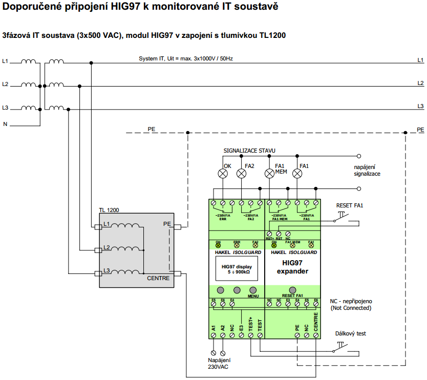
3-phase IT system (3×500 VAC), HIG97 module in a circuit with a TL1200 inductor
Power supply
Remote test
power supply
signalling
STATUS INDICATION
Additional parameters and settings
The two-module concept, offering more free space in the housing, was also used for implementing a high-frequency filter which damps down high harmonics. In fact, the majority of interferences arises from frequency converters at 8 Hz, 16 Hz, etc. The interference filter is another tool which is useful in networks suffering from significant interferences.
The insulation resistance range that can be visualized on the HIG 97 display is 5 to 900 kΩ. The critical insulation resistance Rcrit can be set within the range from 5 kΩ to 300 kΩ. Two independent levels Rcrit1 and Rcrit2 for the signalling relays FA1 (or FA1 MEM) and FA2, respectively, can be employed. Hence, different insulation status levels can be indicated on those relays.
Furthermore, hysteresis of the limiting insulation resistance level can be set from 0% to 100%. This value will apply to Rcrit1 and Rcrit2 simultaneously. It tells us by how many per cent the network insulation resistance must be increased above the Rcrit level for a network resistance fault to stop to be signalled.
In addition to hysteresis, the signalling procedure can be modified by adjusting the ton1 and ton2 parameters, which represent the signalling time delay after the insulation resistance has dropped below the preselected Rcrit level. This delay is displayed in the count-down form. For the extremely rapid FA1 signalling, ton1 is set within the range from 0 to 9.99 with a 10ms step, whereas the ton2 parameter for FA2 is adjustable in seconds, from 0 s to 60 s.
Practical application
The HIG 97 has been tested and then deployed in the heavy industry of continuous steel casting at Třinecké Železárny, where the previously used monitoring devices were unable to reliably measure the network insulation resistance because of frequent transients and interferences from frequency converters.
The monitoring device is installed in the distribution box, where it is connected to a 3×500 VAC / IT network via a TL 500 inductor. It goes without saying that the monitoring device itself as well as the other equipment in the network is protected against overvoltage, by means of a HAKEL SPC 3.0 120 kA DS surge voltage protector specifically designed for IT network protection. The distribution box supplies power to the ABB ACS 800 frequency converters GU1 to GU5. The converters power the 3-phase coils (L11 to L51) of the electromagnetic mixers in the crystallizer. Electromagnetic mixing of the molten metals facilitates their homogenization during the casting procedure, where the melt motion favourably affects the metallurgical structure of the casting.
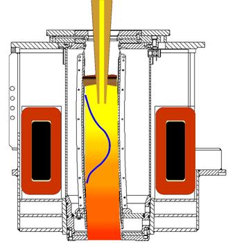
Electromagnetic mixer coil
A section through the crystallizer is shown in the picture above. Molten steel is brought to the crystallizer from the top, and crystallization takes place in the device due to the cooling of the copper component. The mixer coil encompasses this steel flow and acts like a motor stator, i.e. produces rotating magnetic field. The coils are cooled with demineralised water.
And it is this cooling procedure that induces frequent fluctuations of the network insulation resistance. The interferences caused by the frequency converters used make the monitoring device’s mission in such environment even worse.

The HIG 97 has been set to allow more robust measurements, in which transients are not evaluated as faults. The response rate is not decisive here, and so even the slowest reaction rate of 5 seconds could be used in combination with the possibility of using the whole range of the numbers of the monitored network evaluations. In trial operation and subsequently in full use, the HIG 97 insulation monitoring device displayed the current (continuously fluctuating) network insulation resistance, and owing to adequate adjustment of the evaluating algorithm, signals a fault status only in response to a true network insulation failure.