UNGROUNDED POWER SYSTEM MONITORING BY USING HAKEL “HIG” INSULATION MONITORING DEVICES – PART 3
CONSTRUCTION OF THE LONGEST RAILWAY TUNNEL IN THE CZECH REPUBLIC
This next part of the series of papers devoted to applications of HIG insulation monitoring devices, describes the application of HIG device in an IT 22 kV power system.
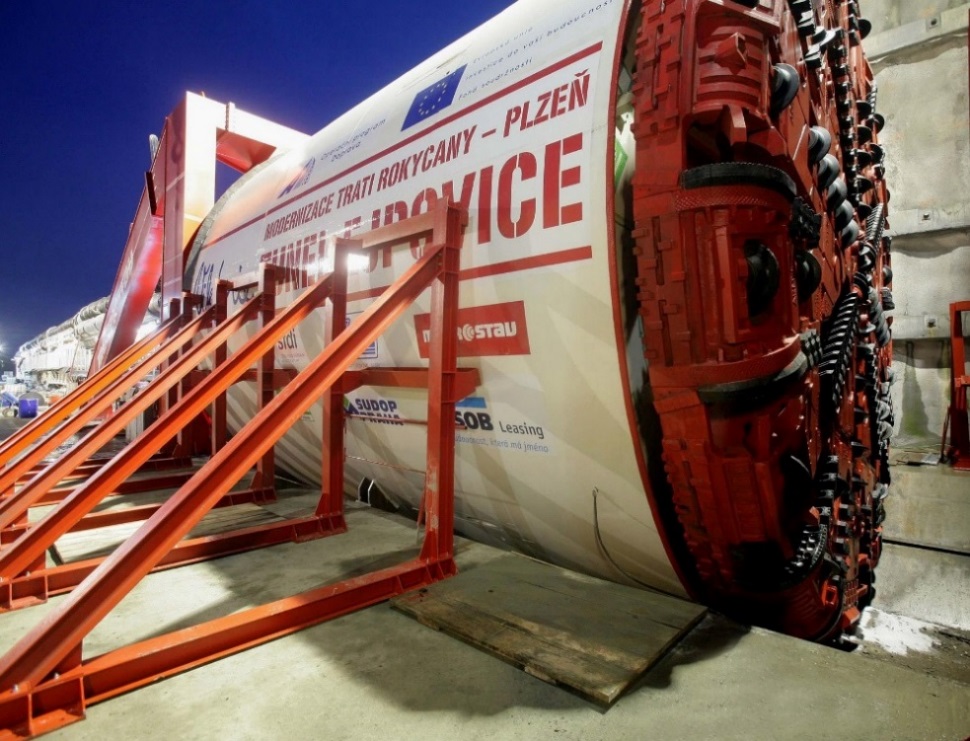
The largest railway tunnel in the Czech Republic started to be built at the Ejpovice site under the Homolka and Chlum hills in late January 2015. METROSTAV a.s. is the construction company building the tunnel. The tunnel on the Rokycany-Plzeň track will have 2 tubes 4150 m each. It will be driven by using the biggest driving shield in the Czech Republic, TBM S-799, christened “Viktorie”.
The shield is 110 m long, its weight is 1800 tonnes and cutting head diameter nearly 10 m. The task ahead is to excavate about 600,000 cubic metres of earth. All shifts taken together, the project will employ 100 workers and 24 engineers and technicians. The cutting head rotates and excavates earth, which falls down into the excavated material chamber. Subsequently, the earth is transported to the surface by means of a screw conveyor. The machine will excavate earth and build the tunnel from special segments at a speed of 2 metres per hour. The facility is expected to build 400 m every month. The system of hydraulic pistons slides out and, backed by the last built annulus of the segmented wall, pushes the whole machine forwards.
Viktorie needs much energy for its work – its power input is as high as 6 MW. Power is supplied to the system from the 22 kV distribution line, routed to a compact distribution board and further on to a 22 kV / 22 kV isolating transformer 6.3 MVA rated power, Dy1 connection. Cables 3 x 22-AXEKVCEY 240, 150 m long, transmit power via special connectors and a drum with a cable 250 m long, to three 22 kV / 400 V transformers installed on the driving shield. The power supply cable unwinds from the drum as the machine is moving forward during the driving work. After the complete 250 m length has been unwound, the drum is connected to a special high-voltage extension and the cable is wound back onto the drum.
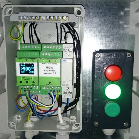
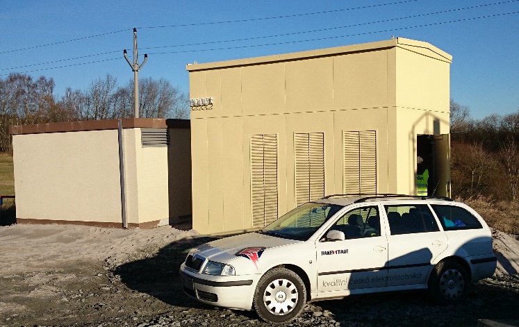
HAKEL s.r.o. in cooperation with REPOS TECHNIK s.r.o. developed a solution for monitoring the 22 kV line insulation status within the segment from the isolation transformer to the transformers on the machine. The 22 kV / 22 kV isolation transformer has an outlet in the secondary winding junction to which a TL22001 HV inductor is connected through an HV cable. To the TL22001 inductor is connected an ISOLGUARD HIG97 version 22 insulation monitoring device (IMD), which is specifically modified and adjusted for this application. The isolation transformer, inductor, IMD, and safety and control equipment are accommodated in a kiosk located beyond the construction site.
The application comprising the HIG97 version 22 monitor with the TL22001 inductor has been tested by the ETD Plzeň short-circuit testing laboratory and subsequently certified by the electrical testing institute EZÚ in Prague and by the District Mining Authority in Plzeň.
The IMD is equipped with a display showing the observed insulation resistance values, with control buttons for device parameter setting, and LED controls indicating the status of the system being monitored and of the device itself.
The HIG 97 IMD can communicate with a master computer via an RS485 industrial bus-bar by using a PROFIBUS-based protocol. The resistance range displayed is from 5 kΩ to 900 kΩ. Furthermore, the IMD includes 4 signalling relays. The ERR signalling relay signals the function of the IMD. As long as the insulation resistance device is OK and the insulation status of a system is being measured, the ERR relay is under voltage and the control is off. This status is signalled by the yellow control on the kiosk. The FAULT2 signalling relay indicates the status of the system being monitored with respect to a preset limit Rcrit2 = 600 kΩ. The FAULT1 signalling relay indicates the status of the system being monitored with respect to a preset value Rcrit1 = 300 kΩ. If the observed insulation resistance is lower than Rcrit2 = 600 kΩ the red control on the kiosk illuminates to indicate a reduced insulation status. A warning sound is simultaneously activated; it can be disabled by means of an external switch. If the observed insulation resistance is lower than Rcrit1 = 300 kΩ the HV switch in the compact switchboard will switch off, thereby disconnecting power supply to the driving shield as a whole. At the same time, the driving shield operators are warned via the GSM gate.
If all the conditions required for the HV switch in the compact switchboard to switch on are met, that is, the IMD is powered and is measuring, the insulation resistance level is higher than the preset value of Rcrit1 = 300 kΩ and the transformer winding temperature is OK, then the driving machine can be reactivated by pushing the activating button.
The IMD is powered from its own consumption switchboard via a 230 V / 230 V isolation transformer to increase the device’s robustness with respect to interferences from the power supply system. This independent power supply voltage allows the entire 22 kV system to be monitored also if no voltage is applied to the system.
A fault signalling delay was set on the IMD in order to reduce the effect of the switching-on power surge of the HV switch on the insulation resistance being measured (elimination of improper disconnection of the system being monitored). This delay can be modified on the IMD display based on accumulated experience with the transient stabilization times.
The insulation resistance limits Rcrit1 and Rcrit2 can be set within the range from 5 kΩ to 890 kΩ by using buttons and viewing on the display. Hysteresis was set on the IMD to 10% of the insulation resistance monitored in order to raise the Rcrit1 and Rcrit2 levels required to terminate FAULT1 and FAULT2 during insulation resistance increase in the system monitored.
Measurement start delay, tSTART = 15 sec, is set on the device for situations when the device is switched on from the OFF status (again, to enable transients on the system monitored to stabilize). Remote IMD performance testing is possible. Access to the IMD setting buttons is locked to prevent misuse. A button combination must be pressed to unlock the device.
During the planned driving shield outages, all the components serving to monitor the system insulation status as well as the performance of the IMD and the control elements are subjected to periodic inspections in compliance with Czech Regulations No. 22/1989 and No. 55/1996.
Information regarding the tunnel driving technology was taken from the website www.metrostav.cz.