MONITORING OF UNGROUNDED SYSTEMS THROUGH THE HIG INSULATION MONITORING DEVICES MADE BY HAKEL – PART 6
FAULT LOCATION IDENTIFICATION
In the previous part of our discussion on the applications of our HIG insulation monitoring devices, we introduced the HIG95+ monitoring device, which is designated for health care. Now, we are going to follow up with a new device from our assortment. It is used to identify fault locations in single-phase IT power supply system.
Fault Location Identification System

Once an IT power supply system insulation condition decreases, the frequent problem rests in the subsequent fault location identification. A technician summoned by the operator would have to gradually disconnect all the individual insulated power supply system circuits in order to identify which of them feature (features) insulation fault. Under full operation, such a disconnecting is very problematic, if not impossible, especially in health care. That is why we developed systems capable of analysing individual power supply system sections and identifying a failed circuit.
There are multiple concepts that one may use for this analysis. The basic solution rests in the addition of an LCI = Locating Current Injector and IFL = Insulation Fault Locator to the IMD = Insulation Monitoring Device. The monitoring device that is already often equipped with its LCI injector and that communicates with IFL, instructs LCI, once the insulation level decreases, to inject the IT power supply system with locating current per the system type and insulation fault scope. This current returns through its path of least resistance to the monitoring device (therefore, if flows through the reduced insulation location). It is then detected by the IFL measuring transformers, which separately monitor every individual circuit. After that, the IFL identifies the fault location through its LED indicators or LCD.
The requirements concerning this equipment are described by the EN 61557-9 norm, which also features the supplemental requirements for insulation fault location mobile identification devices. The identification device may be than used instead of or in combination with a static device. Its operation is based on the hand-held current clamp principle.
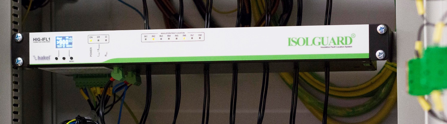
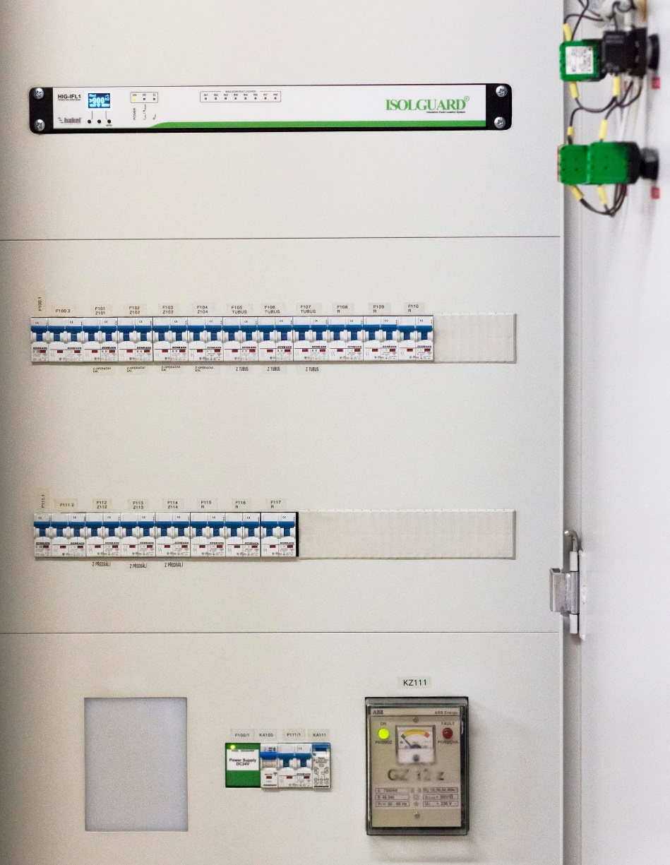
The HAKEL-made device designated as HIG-IFL1 is firmly installed in its distribution box. It belongs to the category of fault location systems (IFLS = Insulation Fault Location System). The IFLS combines both its injector and stabilizer, including its insulation monitoring device. The HAKEL version rests in a module of the rack 19“ standard with the height of 1U. It contains all the specified devices.
HIG-IFL1 Principle
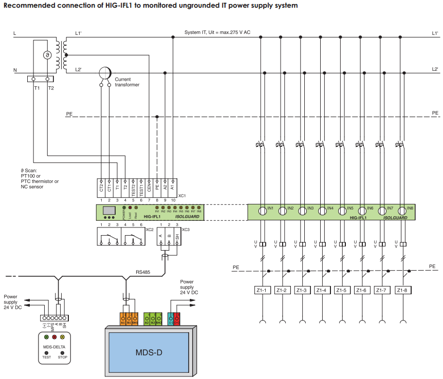
The HIG-IFL1 system’s operating principle is slightly different from the aforementioned basic fault location concept. The measuring of specific insulation levels of the individual circuits continuously takes place with the overall evaluation of the whole IT power supply system’s insulation status. The system continuously generates its measuring pulses; therefore, one injected current is used. The insulation level is simultaneously evaluated in two circuits/inputs (in equipment marked as VSTUP = INPUT), while there are 8 inputs available (IN1 – IN8) for pulling the phase wires through the measuring transformers. The installation is quite obvious from the wiring diagram. A greater number of inputs is possible through extension modules.
Inside, these 8 inputs are divided into 2 groups of four units, and measuring simultaneously takes place in one circuit of the first group of four units and one circuit of the other group. Therefore, during measuring, the front panel always features 2 simultaneously flashing inputs (e.g., inputs 1 and 5). The evaluation of those 2 inputs takes max. 18 seconds. Therefore, all the inputs get measured in max. 72 sec. After that, the system returns to the beginning and repeats the process over and over.
The benefit of the continuous measuring of the individual circuit insulations, compared to fault location only initiated after insulation fault identification, rests in information on the circuit insulation resistance level (in kΩ or MΩ) that may be displayed by the HIG-IFL1 system. As the measuring of the whole power supply system continues, the displayed level is constantly updated. Therefore, if necessary, we know the situation of the individual monitored power supply system circuits.
If the power supply system insulation level decreases, the integrated monitoring device indicates insulation fault. Based on which power supply system circuit the fault occurred in and which of them is currently being measured, fault location takes max. 18, 36, 54, or 72 sec. The monitoring device will continuously signal reduced power supply system insulation level within its regular response time of 5 sec.
Properties of HIG-IFL1
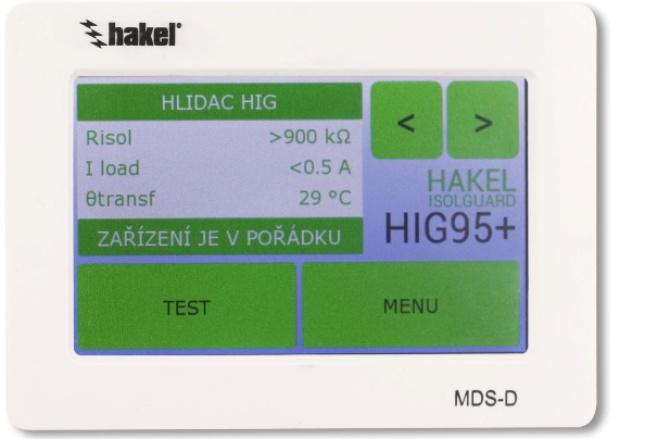
Since the system is primarily designated for health care, the integrated monitoring device is the HIG95+ type, which checks both the insulation level and thermal and current loads of the IT power supply system isolation transformer. These requirements are described in health care by the EN 33 2000-7-710 norm on health care facility equipment. Therefore, the PT100 resistance thermometer, PTC thermistor or thermal break contact may be connected to the HIG-IFL1 and HIG95+ units. You may connect an external current measuring transformer, monitoring the isolation transformer load, as well.
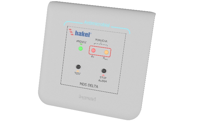
Like in the case of any HIG series monitoring devices, the unit features its RS485 interface terminals for the MDS-D remote signaling panel. Any superior device may be connected to this panel (e.g., PC or PLC), which will use implemented telegrams based on the PROFIBUS protocol for its communication through the RS485 line. Instead of the MDS-D panel, you may connect the innovated simple MDS-DELTA information panel to the RS485 terminals.
The HIG-IFL1 system is usually fed from its monitored IT power supply system; however, it may be connected to its external power supply. Resultantly, you may monitor even a power supply system without any power (e.g., before it is turned on). The other terminals are designed for the monitoring device remote test. One contact is to be used for monitored power supply system insulation fault signaling, and 1 for the signaling of thermal overload or overcurrent of the isolation transformer.
The panel front section features not only its signal LED that indicate ongoing measuring or faults of the individual inputs, but also other LEDs that signal the available system power supply, system overcurrent or thermal overload condition and insulation level decrease below the set critical resistance value. There is also the
integrated monitoring device LCD with its buttons for the same control method as we know it from the HIG monitoring device series.
The parameter settings derive from HIG95+, and they were described in detail in the previous article.
HIG-IFL1 Installation and Commissioning
With the support of the HAKEL Company, the HIG-IFL1 system was installed into the switchboard of the surgery room power supply of the surgical ward of the Pardubice Hospital. It was the first complete replacement of its existing solution of the end of the 90s with a modern system allowing insulation level decrease location identification.
The original monitoring device used to use its analogue barograph to monitor insulation resistance against the ground of a single phase IT power supply system with the rated voltage of 230 V AC. It used to be fed through this power supply system as well. With the floating contact of this monitoring device and contactor logic, the surgery room was equipped with its audio visual fault alarms, including the possibility of monitoring device testing through a specific button. The same alarm options were also provided by the switchboard front panel. The isolation transformer used in this installation reaches the output of 3.15 kVA. Its centre terminal is available on the secondary side, and it features two thermal break contacts that signal winding overheating.
The new solution includes the HIG-IFL1 system. The IT power supply system is divided into its seven independent circuits, which feed the surgery room outlets. Both wires of every circuit are led through the separate HIG-IFL1 inputs. Every circuit features its double pole protection against entering HIG-IFL1. For the purposes of insulation level monitoring, the monitoring device is connected to the grounding connection (PE terminal) and isolation transformer secondary side centre (CENTRE terminal). The system monitors the 50 kΩ insulation resistance critical value. The HIG-IFL1 system is fed through a backed up TN-S type power supply system, which also feeds the isolation transformer. Thanks to this arrangement, HIG-IFL1 allows the measuring of the monitored system and also evaluating of fault locations before IT power supply system activation.
To monitor the isolation transformer load, a current measuring transformer with its conversion ratio of 30/5 A was installed. The critical current limit overload is set to 13 A in the HIG-IFL1 system. This value is set due to the isolation transformer output current that reaches 13.7 A during the transformer’s maximum output of 3.15 kVA and 230 V. The isolation transformer thermal overload is monitored by a contact type sensor. The two temperature contacts offered by the transformer are connected into a series and led directly to HIG-IFL1. The remaining system settings, including its time delays or critical value hysteresis were left at their initial values that are recommended for the majority of hospital applications.
The remote signalling is completed through the combination of the MDS-D panel and monitoring device floating contacts. The MDS-D touch panel was installed in the surgery room to operate as alarm for the personnel. Communication with the HIG-IFL1 system takes place through the RS485 bus. The system is fed by the HAKEL DC24V power supply. To keep the alarm at the switchboard location, two signal lamps were attached to the switchboard door – yellow one for insulation level fault, red one for transformer overload. The alarm comes with a button for testing the whole HIG-IFL1 system. These features were secured through their floating contacts and inputs, which the HIG-IFL1 system offers as well.
Upon installation completion, the whole power supply system was measured and carefully tested. Every power supply system outlet was tested through a 47 kΩ test resistor. In all the cases, insulation level fault alarms were immediately initiated, and fault locations were identified correctly in their corresponding circuits.