SURGE and PERSONAL PROTECTION
focusing on traction systems, vehicles and facilities
Modern electronic systems are more and more sensitive to increasing electromagnetic interferences, which may affect the systems and cause their failure and even destruction. So, the use of surge arresters appears to be a necessity today (see EN 62305).
Although DC traction lines never served as power distribution systems, nowadays they are used quite extensively to power various facilities near the trolleybus and tram lines, such as rail points, ticket machines, cameras, tram/bus stop lighting systems, voice systems, as well as security systems, rail lubricators and point heaters, etc.
Powering such systems has always posed problems due to transition and switching phenomena, causing voltage surges in the lines. In DC traction lines, the affected facilities also include the AC/DC traction and, where used, control of rectifiers with IGBT transistors.
Without external enhancement, surge arresters integrated into the devices are unable on their own to adequately protect facilities powered from the DC traction line. In fact, three-step protection must be applied, taking into account the non-standard overvoltage peaks in the line.
Overvoltage sources:
- direct or indirect strike of lightning hitting the traction lines, rectifier substation buildings, HV lines supplying power to the substations. Induction into the traction systems
- passing through a section break (also under voltage)
- regenerative braking (braking while passing through a section break), short but power-demanding peaks
- regenerative braking and passing through section breaks between two rectifier substations (worst case)
- bay switching in substations
- overvoltage in rectifiers and their interactions in the substations
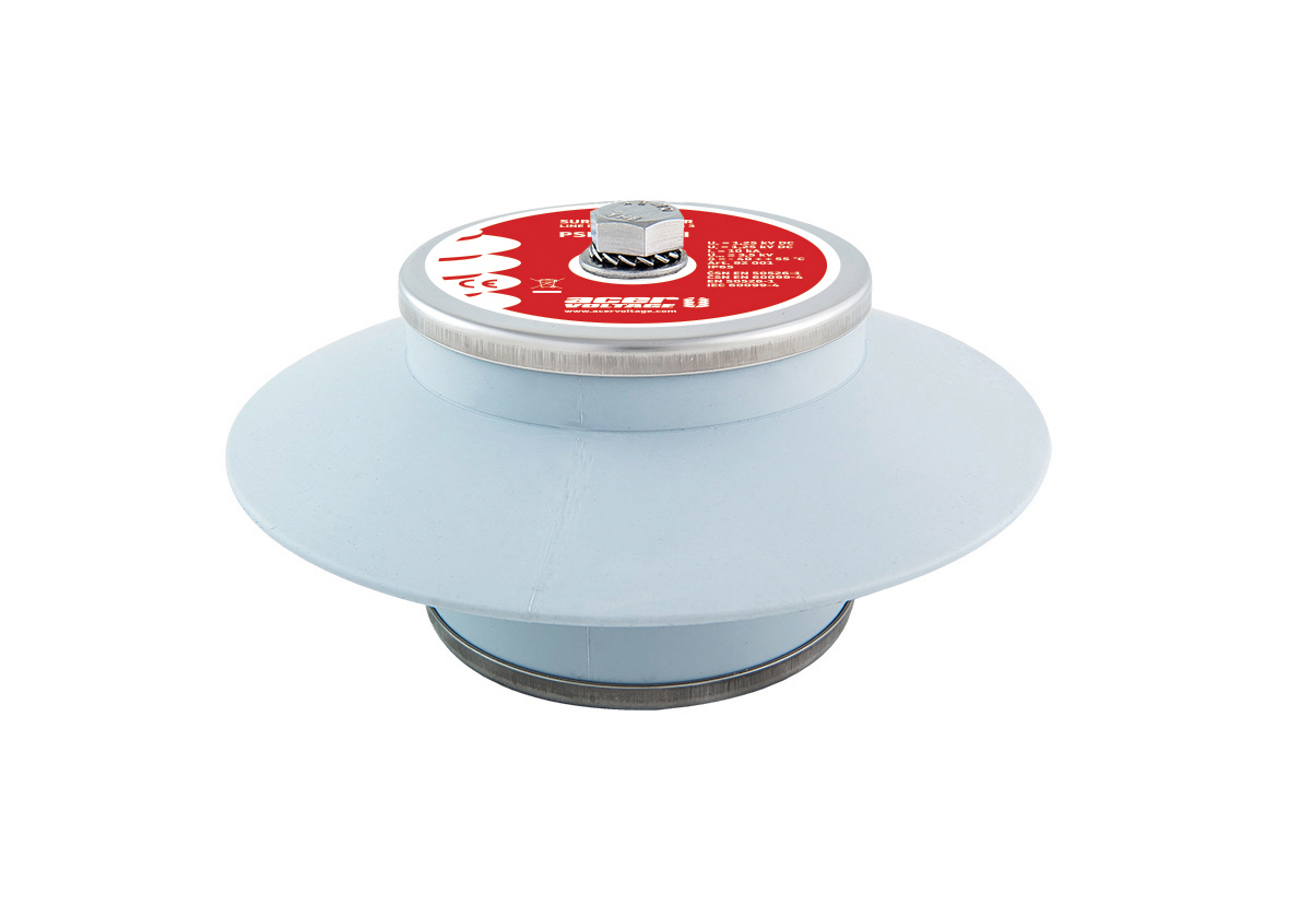
The PSP 1/10/III overvoltage limiter, manufactured by the Czech company ACER HK, has been used with success to protect rectifier substations, traction lines, facilities and vehicles.
This overvoltage limiter consists of a varistor pile housed in a glass-reinforced plastic tube, the whole system being embedded in a silicon rubber casing.
The Uref level, (voltage at which a 3 mA current starts flowing through the varistor) is about 1.7 kV at a 10 kA rated discharge current. This Uref level is reduced to 1.3 kV in the newly manufactured PSP 1/10/III SL model. Residual voltage is 3.3 kV (or 2.5 kV in the SL model).
Rectifier substations
Installation of surge arresters on both the HV side and the LV side should be considered when designing the protection system against overvoltage. On the HV side, this task should be the responsibility of the power distribution company. On the LV side, Type 1 lightning current arresters should be installed downstream of the transformer to protect the substation input from switching overvoltage (HV system handling) and from atmospheric overvoltage (lightning strikes and induction into the line).
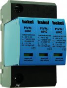
Installation of Type 1+2 surge arresters (such as PIV-720 DC / 1000 DC from the Czech company HAKEL) is advisable on the DC side downstream of the rectifiers in the bays in order to limit overvoltage arising in the traction power lines and also affecting the rectifier’s DC side.
Traction line
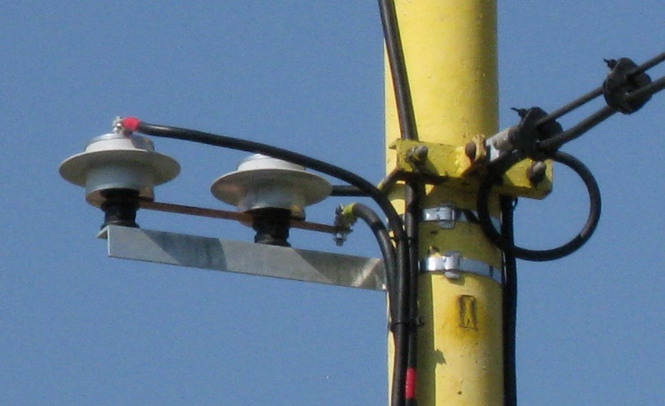
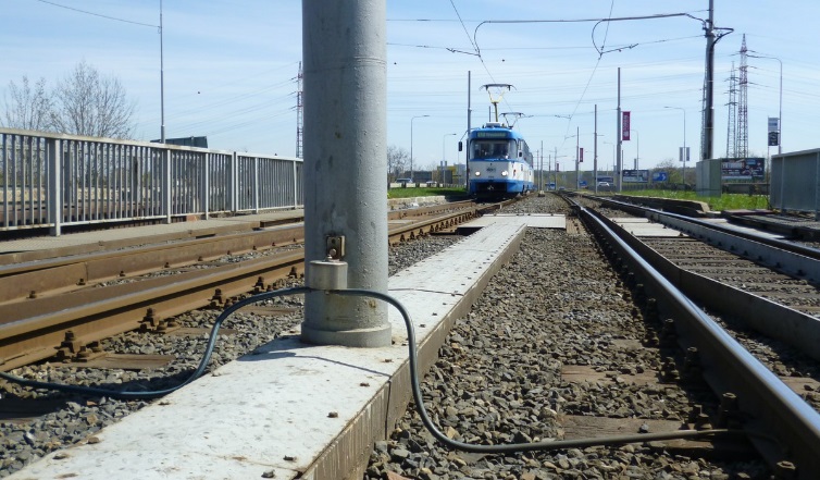
On tram lines, the PSP limiter is installed directly on the poles between the overhead line and the rail. On trolleybus lines, the limiter is installed between the plus pole and earth and between the minus pole and earth.
Installation of surge arresters also between the plus and minus poles at the traction line ends (loops) is recommended for trolleybus tractions to limit transverse overvoltage.
Vehicles
Limiter types identical with those installed at the lines are used on the trolleybuses and tram wagons.
Comprehensive solution
When designing a comprehensive solution, surge arresters must be installed in the rectifier substations and uniformly along the whole traction line, at rail points, and at facilities transforming the traction line voltage to small voltage. Type 3 surge arresters must be installed into electronic devices (unless already present) to protect the devices from induction. All inputs to the protected systems, such as current loops and data inputs, must be protected. The protection against overvoltage will be enhanced by installation on the vehicles.
Surge arresters will reduce appreciably both operating overvoltage and induction from atmospheric overvoltage events and improve the reliability of the entire system operated.
Low voltage limiter
HL120 is a low voltage limiter (LVL acc. to EN 50122-1) intended for the protection of non-live parts of metal structures in AC or DC traction systems. It is used for the effective protection of people who might come into contact with these parts during a lightning stroke or in the case a fault of traction lines. HL is installed directly on the protected construction structure (using two M12 bolts) so that if it is activated, it creates a conductive connection between this structure and the 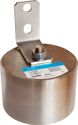
tracks. The principle of the HL construction is based on the parallel connection of three non-linear elements (1 high power metal oxide varistor MOV plus 2 high-performance thyristors) built into a stainless steel cover. If the HL is activated by lightning current or current from the contact of the protected metal structure with for example a fallen trolley line, this current is instantly shorted to the track by the fast reaction of the MOV (the standardly given time of its reaction is 25 nsec). The maximum value of this current’s amplitude may be 40kA (10/350). For the duration of activation of the MOV a voltage protection level about 500V is formed on it.
So that the heat released in the MOV does not damage its structure, a delay element is built into the HL hardware which for approximately 1msec ignites both the built-in high performance thyristors, and this moment is derived from the VPL on the varistor. According to the polarity of voltage on the MOV, the relevant thyristor from the built-in pair is activated and it takes up current which to that time have been conducted by the activated MOV. Depending on the immediate current value of the passing current, the voltage level drop on this thyristor can be in the range 1÷3V. If the arising activation current is significantly lower than the maximum working current of the used thyristor, this process can last up to tens of seconds (for the HL120 this process is characterised by the typical value 300A/60sec… reversibly), which corresponds to the charge passing through of 18000 Asec.
A large power loss is on the thyristor for the time of its activation, and so the construction of the HL sleeve is based on the principle of conducting the released heat to its metal outer casing and then via this casing to the construction building structure. One important requirement of the HL is the assumption of the creation of an internal short circuit in the case of the voltage, current or heat overloading of the built-in MOV, which is met in the case of the HL internal construction described above.